Loop Powered Indicator Wiring Diagram
Wire loop powered connections devices power supply example indicator external back basics figure Instrumentation loop diagrams Loop wiring diagram examples
DP32: Loop Power Indicator | WISCO INDUSTRIAL INSTRUMENTS
Ma 20 current loop wire powered loops system use temperature figure easy made sensors typical Loop power powered devices instrumentation indicator basics animation gif instrumentationtools Instrumentation wiring instrumentationtools
Instrument instrumentation signal
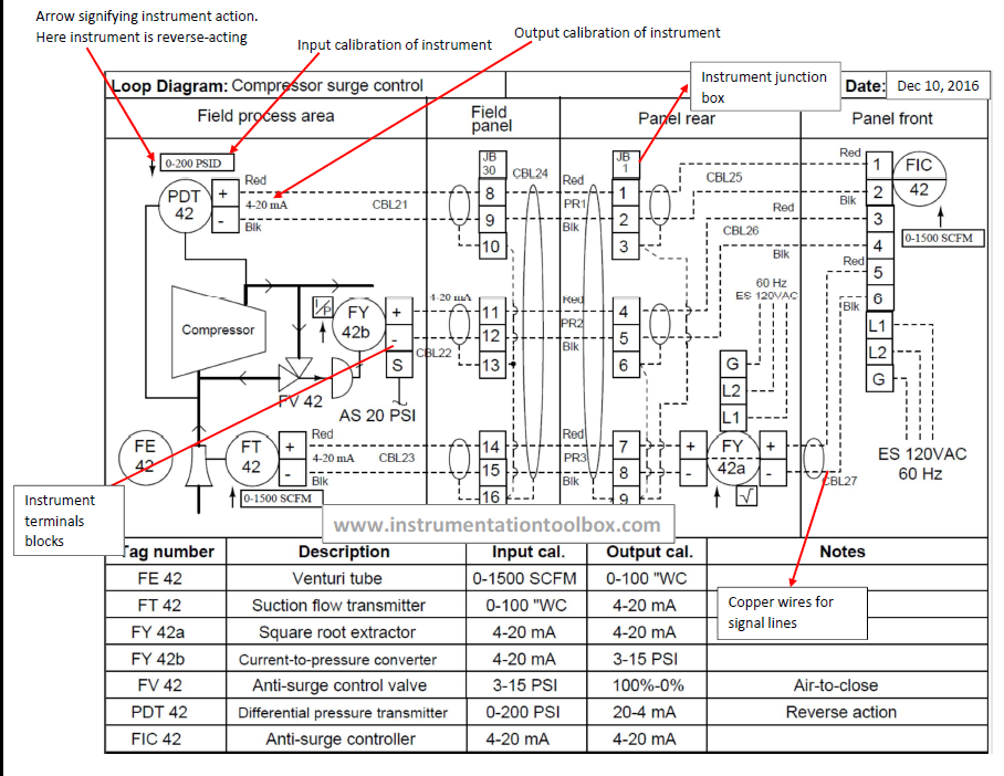
Dp32: loop power indicatorWiring loop diagram examples instrument diagrams do Instrument loop diagram basics4-20ma current loop devices.
Loop instrumentation diagrams sample diagram instrument control level flow instrumentationtools controller signal hart read next calibrationHow-to create instrument loop diagram? What is loop wiring diagram4-20 ma current loop.
![4-20mA Current Loop Devices | Circuit Cellar](https://i2.wp.com/circuitcellar.com/wp-content/uploads/2020/01/352_Hildreth_Figure_4.png?w=810&ssl=1)
Back to basics: the fundamentals of loop-powered devices
Basics of loop powered devicesLoop powered indicators Loop current ma 20 wiring diagram devices 20ma transmitter circuit connecting adc port figure standard without supportLoop instrument instrumentation ild diagrams transmitter pressure marshalling engineering mounted.
Dp32 indicator wisco20ma fundamentals 4 to 20 ma current loops made easy.
![Loop Powered Indicators - Status Instruments](https://i2.wp.com/www.status.co.uk/wp-content/uploads/DM700-MKII-web-image-set-1928x2048.jpg)
![What Is Loop Wiring Diagram - Wiring Diagram](https://i2.wp.com/instrumentationtools.com/wp-content/uploads/2016/11/instrumentationtools.com_instrumentation-loop-diagram.png)
![Instrumentation Loop Diagrams - InstrumentationTools](https://i2.wp.com/cdn.instrumentationtools.com/wp-content/uploads/2020/06/Sample-Loop-Diagram.png)
![4-20 mA Current Loop | Basic Fundamentals](https://i2.wp.com/www.instrumentationblog.com/wp-content/uploads/2020/10/4-20-mA-Current-Loop-with-Fuse.jpg?resize=770%2C569&ssl=1)
![Basics of Loop Powered Devices - Inst Tools](https://i2.wp.com/cdn.instrumentationtools.com/wp-content/uploads/2016/05/instrumentationtools.com_loop-power-indicator-animation.gif)
![DP32: Loop Power Indicator | WISCO INDUSTRIAL INSTRUMENTS](https://i2.wp.com/wisco.co.th/main/sites/default/files/DP32_Block_Diagram.png)
![Loop Wiring Diagram Examples - Wiring Diagram](https://2.bp.blogspot.com/-tPUXuRo4JUE/WExv0jGzuQI/AAAAAAAACZA/_hNLceV4QDEmwnkt9NE3Fxv6ndDuEXDRQCLcB/s1600/Instrument%2Bloop%2Bdrawings.png)
![4 to 20 mA Current Loops Made Easy | Harold G Schaevitz Industries LLC](https://i2.wp.com/www.hgsind.com/sites/default/files/content_images/currentloop_fig3.jpg)
![How-to Create Instrument loop diagram? | Marshalling Loop Diagrams](https://i2.wp.com/cdn.instrumentationtools.com/wp-content/uploads/2019/01/Instrument-Loop-Diagram-657x400.png)
![Instrument Loop diagram basics | Instrumentation](https://i2.wp.com/instrumentationbasic.com/wp-content/uploads/2021/06/loop-diagram-1-1024x488.jpg)
![Back to Basics: The Fundamentals of Loop-Powered Devices | Precision](https://i2.wp.com/www.predig.com/sites/default/files/images/Indicator/back_to_basics/loop_powered_devices/2_wire_connections.png)